

How To Remove The Camera Lens From A Samsung Note 5
Introduction
Follow this guide to remove and supercede the rear-facing camera module for the Galaxy S10. The module includes all iii rear-facing cameras, also as the frame that holds them.
Depending on where you bought your S10, the camera module may be dissimilar. Check your phone and replacement function before following this guide.
This procedure requires removing the motherboard. The hardest part is removing the back comprehend.
-
-
Insert a SIM carte du jour squirt tool, SIM eject bit, or a straightened paperclip into the hole on the SIM tray, located at the pinnacle border of the phone next to the plastic antenna band.
-
Press firmly to eject the tray.
-
Remove the SIM bill of fare tray.
-
-
-
Unplug and power off your telephone before you begin.
-
Heat an iOpener and apply it to the back cover's right edge for two minutes.
-
As yous expect, take a expect at the image of the removed back cover and take note of where the agglutinative is located.
-
-
-
Rest the heated right edge of the phone on something that is about 0.5 inches (13 mm) thick. This angles the phone for the opening tool.
-
Caryatid the left edge of the phone with your fingers so that the telephone won't slide. Pull on the suction loving cup with business firm force per unit area.
-
Press the edge of an opening tool into the seam betwixt the back encompass and the frame.
-
With the opening tool in identify in the seam, slide it back and forth along the seam to loosen the back cover.
-
-
-
Estrus an iOpener and apply it to the same edge of the phone for two minutes.
-
Apply a suction loving cup to the back of the telephone, equally close to the center of the right edge as possible (where the adhesive is narrowest).
-
Pull on the suction cup with strong, steady force to create a gap between the back embrace and the frame.
-
Insert the indicate of an opening pick into the gap.
-
If y'all are having problem creating a gap, your all-time bet is to apply more rut to the edge and try the previous pace once again.
-
Yous can effort applying a few drops of high concentration (over 90%) isopropyl alcohol into the seam to help loosen the adhesive.
-
-
-
Slide the opening pick forth the edge of the phone, slicing through the adhesive.
-
Go out a selection in the seam to prevent the adhesive from re-sealing.
-
-
-
Employ a heated iOpener to the lesser edge of the phone for 2 minutes.
-
Insert an opening pick into the right border near the lesser right corner.
-
Carefully slide the pick effectually the corner. Keep cutting along the bottom edge and around the bottom left corner.
-
Leave an opening choice in the seam to preclude the agglutinative from re-sealing.
-
-
-
Continue heating and slicing around the remaining edges of the phone.
-
-
-
Once you lot accept sliced around the phone, twist an opening choice in one of the edges to help dissever the back cover from the frame.
-
Lift the back cover slowly. Use opening picks to piece whatsoever remaining adhesive.
-
Remove the back cover.
-
-
-
Remove the eight 4 mm Phillips screws securing the top midframe to the telephone.
-
-
-
The midframe is still held in place past a few plastic clips around the edge.
-
Insert the point of a spudger into the notch on the correct edge of the midframe, virtually the book upward button.
-
Pry up to loosen the midframe from the phone.
-
-
-
Lift the midframe from the top corners and remove it from the telephone.
-
To reinstall the superlative midframe:
-
Align the midframe's top edge to the telephone and lay the frame downwards on the telephone.
-
Use fingers to apply pressure along the midframe perimeter to snap the midframe clips back into place. The edges should sit affluent confronting the telephone edge.
-
-
-
Insert the flat end of a spudger underneath the battery connector, which is attached to the motherboard below the rear-facing camera.
-
Pry upwards to disconnect the connector from its socket.
-
Gently push the battery'south flex cable away from the motherboard socket to foreclose accidental contact.
-
-
-
Remove the vii 4 mm Phillips screws securing the lower midframe.
-
-
-
Insert the point of a spudger underneath the top correct corner of the lower midframe.
-
Pry up to release the midframe from the phone.
-
-
-
Grasp the loosened end of the midframe with your fingers and lift upwards slowly.
-
Jerk the midframe slightly to assist release the remaining edge clips.
-
Remove the lower midframe. The loudspeaker is built into the lower midframe.
-
-
-
Employ the flat end of a spudger to pry up and disconnect the display connector from its motherboard socket, located near the lesser right corner of the phone.
-
-
-
Employ the bespeak of a spudger to pry up and disconnect the headphone jack's connector from its motherboard socket.
-
-
-
Remove the three three.7 mm Phillips screws securing the motherboard to the phone.
-
-
-
Insert the point of a spudger underneath the right edge of the motherboard, well-nigh the volume down push.
-
Pry up gently to loosen the motherboard from its recess.
-
-
-
Insert the point of a spudger under bottom left corner of the motherboard.
-
Pry up gently to loosen the motherboard from its recess.
-
-
-
Using your fingers, grasp the motherboard past the top corners.
-
Swing the motherboard slightly out of its recess. Be conscientious non to snag any cables along the mode.
-
Pull the motherboard towards the height edge of the phone while fluctuant the board slightly. This will loosen the charging port from its socket.
-
Once the charging port is freed from its socket, remove the motherboard.
-
Align the motherboard's charging port with the bottom edge of the phone.
-
Gently push the motherboard against the bottom edge of the phone until the charging port is completely seated.
-
Lower the motherboard and press into identify. Be careful not to trap any cables underneath the motherboard. The board should sit down flush confronting the frame.
-
-
-
Flip the motherboard over.
-
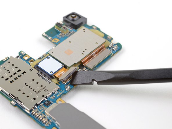
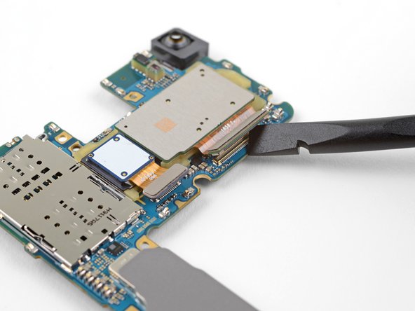
Employ the apartment stop of a spudger to pry upward and disconnect the two camera connectors from their sockets on the motherboard.
-
-
-
Heat an iOpener and lay it over the rear-facing camera module for one minute.
-
-
-
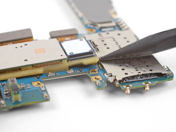
Insert the point of a spudger under the top-left corner of the camera module, where there is a small-scale notch.
-
Pry up to loosen the camera module from the motherboard.
-
-
-
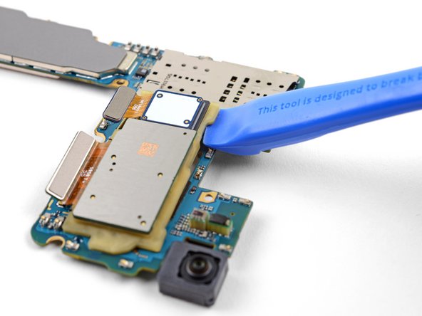
Insert the edge of an opening tool under the loosened corner of the camera module.
-
Pry up to release the camera module from the motherboard.
-
-
-
Remove the rear-facing camera module.
-


Determination
To reassemble your device, follow these instructions in reverse order.
Embed this guide
Cull a size and copy the code below to embed this guide as a small widget on your site / forum.
Preview
Source: https://www.ifixit.com/Guide/Samsung+Galaxy+S10+Rear-Facing+Camera+Module+Replacement/121825
Posted by: cookboun1947.blogspot.com
0 Response to "How To Remove The Camera Lens From A Samsung Note 5"
Post a Comment